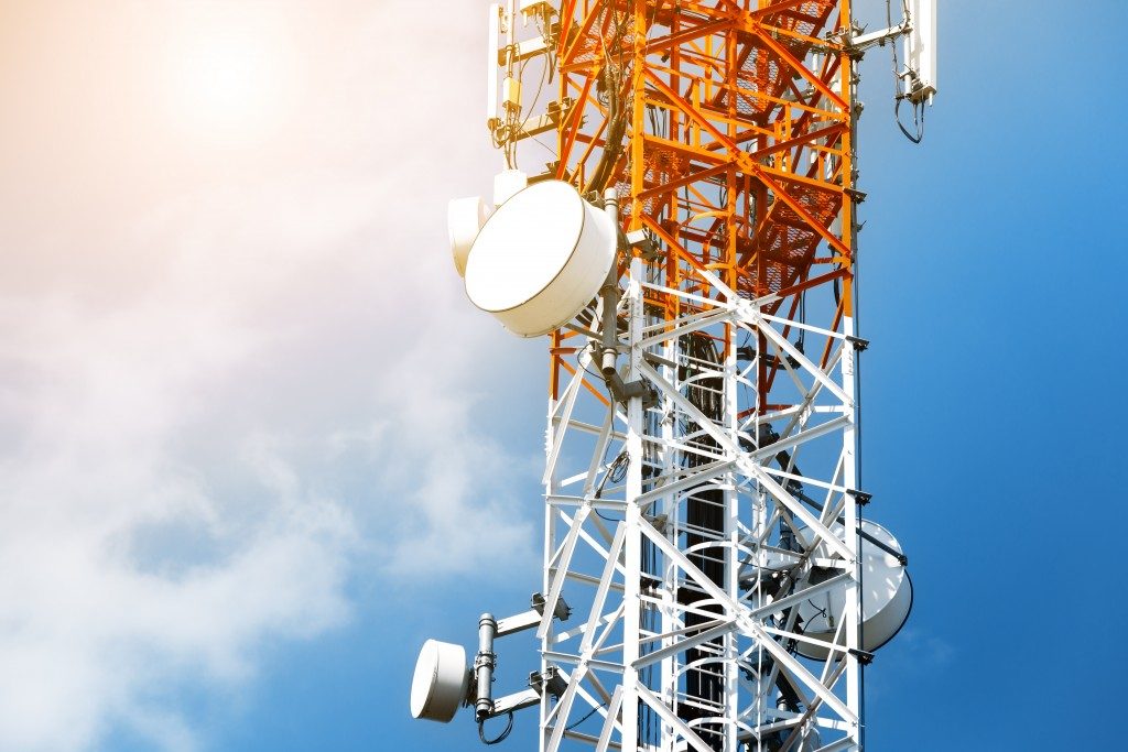
Antennas, from a user’s perspective, are the primary interface between GNSS satellite constellations (or space segment) and a GNSS receiver (or user segment). The antennas capture the signal from space and then use them to determine the position of a user. Generally, the antennas used in GNSS receivers comprise a radiating element installed on a ground plane. An amplifier in the antenna is designed to set the receiver’s noise figure while a radome protects it.
With the high risk of jamming for GNSS antennas, the ideal antenna for your device would be a controlled reception pattern antenna (CRPA). CRPA simulation will guarantee that the antenna works for your positioning device and explores its spatial diversity. Unwanted jamming signals will arrive from all directions while the right signal only comes from a particular direction.
In spatial diversity, the CRPA will filter all signals from directions other than the correct one. This way, the risk of jamming is reduced in your device. The following are tidbits on the characteristics of the antenna you should use in your GNSS receivers.
Antenna Power
GNSS antennas, in general, need no electrical power for them to work and are hence called passive antennas. These antennas must connect with your receiver’s front end for signal amplification. If, however, the antenna is placed away from your receiver such as in rooftop antennas, you can implement the signal amplification in the antenna.
In this approach, your antenna will be an active antenna that amplifies a signal and makes up for the potential losses in your coaxial cables. You might also need to add a low-noise amplifier (LNA) to your antenna setup in this case.
Phase Center
When your receiver generates a position, it is estimating the electrical phase center’s location of your antenna. This is the point where signals will be captured on your antenna irrespective of its distance for your receiver.
The physical phase center of your device is a constant but the electrical phase center varies based on the direction of a signal’s arrival. You should ensure you determine the phase center of your GNSS device accurately, more so if you want to generate millimeter positioning resolution.
Signal Bandwidth
 The RF section of your GNSS receiver should consider the signal structure it receives and selects as per a device’s front-end specifications. GPS antennas typically process signal bandwidths of 1-2% of their signal center frequency. As such, an antenna yielding not less than 20 MHz bandwidth in L1 will suffice for most applications.
Out-Of-Band and Noise Rejection
The signals a GNSS receiver will receive are weak, and they are further distorted by the noise from your receiver and connecting cables. To boost the quality of your signal, you can use two-staged low noise amplifiers. A passband filter before the amplifier will also boost the signal received.
There are different tools used for CRPA simulation to guarantee the antenna you pick will meet the above design characteristics and still protect your device from jamming. You should opt for a tried and tested manufacturer for your simulation device. This is the best way to guarantee that your GNSS receiver is unaffected by jamming and spoofing and meets your clients’ needs.
